Wednesday, November 30, 2011

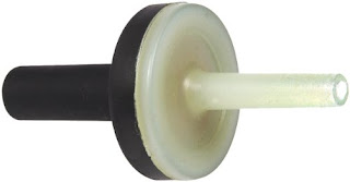
A great feature. And a Non-Return Valve (Check valve)

3 ความคิดเห็น
Considerations in choosing a valve to return.
Material (material).
           The valves are to be used for a variety of common tasks. To the water. That must withstand high pressure natural gas applications. The high corrosion resistance and chemical And to withstand heat and high pressure steam, etc., so the materials used to make the valve must be selected to suit the material (medium) in the pipeline.


           Of the PTT. The Check Valve Material used in natural gas should be a standard reference Cast Steel or Forged Steel ASTM A 216 Grade WCB standards ASTMA 105 Grade 2.

           In addition, each type of material to withstand the pressure and temperature. (Pressure / temperature rating) are different, which is known to be resistant to a variety of materials with different materials, a Stress. When adding more pressure. Will withstand temperatures down. Or it can withstand higher temperatures when the pressure decreases. We need to bring the pressure and temperature were compared with actual use. pressure / temperature rating of the valves of each type of material so that the material can withstand the pressure and temperature conditions of use.


           Major components of the valve is reversed and the renewal of the valve spring and the spring is a good idea I can not Stress fracture Life cycle has a high resistance to corrosion. And the pressure in the open or under a Range of Pressure drop of the spring stiffness to suit a wide range of applications. The material is Stainless steel springs in general, but if you use a high temperature over 300 should be a spring made from Inconel.

           For selecting the material of the Seal, which determines the rate of leakage (Leakage rate) of the valve is to be divided primarily into two categories: Metal to metal seal and Soft seal by Soft seal the Leakage rate is better than Metal. Zero leakage to metal seal, or a material that is Soft seal must be selected to suit the material. Pressure and temperature inside the pipe. The materials used in the Seal Check Valve is widely used in the work.


           Natural gas and BUNA-N or Nitrile Rubber, synthetic rubber, which is caused by the mixture. acrylonitrile (ACN) with Butadiene leak rate testing (Leakage rate) of the valve and return valve between the product manufacturer to do it. There are several standard benchmark tests, depending on each manufacturer to choose from. The popular standard is the European standard (EN), German Standard (DIN) and American standards (API).

Pressure drop (Pressure drop).
           In the design of piping systems as well. Pressure drop across the pipe should not be more than 0.3 bar, the pipe length 100 meters, Pressure drop caused by friction of the surface of the pipe itself. Pipes, valves and fittings installed at all. Therefore, the valve is back to keep the pressure should not exceed 0.1 bar Pressure drop across the valve, or one of them.


Valves are to be classified into three main types.
1. Valve and back pressure drop across the valve between DISCO and DISCO to be most valuable when compared with the other two types because DISCO has obstructed the flow than others. Thus, it often does not produce an 8-inch valves of this type because it is too high Pressure drop Pressure drop through the valve will be different depending on the stiffness of the spring as well.
2. Valves and back pressure drop across the valve, Swing and Swing back to DISCO is lower than the valve is open and unobstructed flow of less than The opening angle is about 600 -700 but also Pressure drop than the Dual plate.
3. Valves Dual plate similar to a pressure drop across the valve and back Dual plate to a minimum. The valve opening and flow, very little obstacles. The opening angle of about 800 each.

Valve to return to the good quality.
           - Pressure drop is constant and appropriate to the system.
           - Sealed (Tightness of the valve) or Leakage rate is low.
           - Lifetime of the spring (Spring life time) life does not crack.
           - Requires a minimum flow rate (Min flow), to avoid problems Clattering.


           The installation of Check Valve.
           In the case of a Check Valve to prevent back pressure to the gas station. Turbine meter must be installed from a 5D (5 times the pipe diameter) standard AGA7.

           Clattering is a phenomenon that the valve has a flow rate or pressure is not enough to cause the valve to the open position or the position is stable. Often resulting in a short time. At startup or stop the system. The valve will open - the frequency and causes wear and tear. If the valve has been selected the wrong size or type Clattering the time of normal use. The valve due to wear and short-lived than it should be.

           The size of the valve to return (Size) is the size of the valve to return often overlooked by those who use it. Because the majority of the selected pipe size alone. The installation is convenient, but if we take into account the pressure drop across the valve should not exceed 0.1 bar, and to avoid instability problems, the valve opens. Clattering known that the short lifetime of the valve. Selecting a pipe, valve size alone is not sufficient to check the pressure drop and Clattering with

Check Valves- Pair

Tuesday, November 29, 2011

Installed Control Valve Flow Characteristics

0 ความคิดเห็น
Control Valve Flow Characteristic Curve showing the relationship between control valve capacity and range of motion of the valve stem of the valve which has a different design, Trim it. Indeed, by its very nature, valves typically have a non-linear behavior, but the design is different Trim enables Control Valve Flow Characteristic. In various ways as shown.

Inherent Control Valve Flow Characteristics.

The above was compiled. characteristics. Can be found often on% volume flow through the valve can be plotted versus the distance of movement of the valve stem on the condition that the pressure loss through the valve needs to be fixed, we refer to grap that the inherent flow characteristics. By the following graph.


Linear - the volume of flow will be greater when compared to the movement of the valve is in a straight line.
Equal percentage - the amount of flow will be greater when compared to the movement of the valve to the line exponentially.
% Change in the movement of the valve is equal to% change the value of Cv.
A modified parabolic characteristic. Centered approximately linear and equal%.
It has good control on the flow volume is less. And a linear behavior at higher flow.
Quick opening of the flow is changed while the valve is opened from the closed position, indicating that the valve has a high gain is not commonly used in control. It is only used for on-off, as in the sequential system is a batch or semi-continuous processes.
Hyperbolic.
Square Root.
Primarily used in control systems and control valves with flow characteristic curve is linear, equal-percentage, or modified-flow characteristics.

Installed Control Valve Flow Characteristics.

When the valves are installed in the piping system. Transmembrane pressure across the valve is not fixed, is proportional to the movement of the plug to draw a graph of the actual flow% compared with the opening of the valve. The resulting graph is called Installed Flow Characteristic.

In most cases, when the valve opens up a part of the flow in the pipe before it reaches the valve, which will result in the loss of pressure lose a lot of pressure to it. Since the resistance of the pipe it. In this case, it will keep the pressure before the valve P 1 decreases the pressure drop across the valve decreases, which results in movement of the graph and the curve that is Installed Flow Characteristic Curve by me. an example.

The curve is linear up to look like the quick opening.
curve will shift up to an equal% similar to a linear curve.

Pressure Relief Valve

0 ความคิดเห็น
Pipelines used to transport fluid as well as various components of the system must be. Designed to withstand the maximum pressure (Maximum Allowance Pressure, MAP), the value of one if the pressure of fluid in the system is raised. The rise. Pressure can occur in two cases.
1. The source of pressure on the pressure. With increasing pressure.
2. The fluid is compressible in E system, which is caused by the volume of fluid flowing out of less. Than the amount of fluid that flows into the system when the fluid. Higher pressure. G more than a piping system or equipment. Production system that is resistant to the piping system or equipment, they will have to break or explode due to system designers need to be equipped. The pressure from the system when the system pressure exceeds the pressure was off the devices in the system are able to prevent the girl with the normal problems touch with the girl up on the property. Union County and the organism. Equipment used for installation purposes. Prevent over-voltage conditions. (Overpressure) and safety valve (Safety Value), pipes (Vent), the overflow pipe (Over Flow) Rupture Disc and so on.
Safety valve (Pressure Safety / Relief Valve) is a device installed in a piping system used to vent excess pressure from the system. Internal safety valve as shown below. A safety valve when the pressure Of fluid in the system, rather than the pressure of the spring. Customizable built-in safety valve. Pressure of the fluid. Pushes the valve lift of the valve seat, fluid is drained from the system. When the system pressure drop. And the voltage drops below the pressure to win. It's spring in the valve. Pressure valve is down. Turn off the valve seat. Fluid can not drain out. Of the future. In the spring pressure of the safety valve must be set to discharge pressure safety valve. When the pressure exceeds the standards set. Or under the laws of each country is defined as the standard of the American Society of Mechanical Engineers (ASME) imposed on the device, the pressure of burning (Fire Pressure Vessel, ASME I) for example, boiler spent (Boiler) valve. New products will have to drain the excess pressure in the system. (Overpressure) by allowing the formation of the Industry (Accumulated pressure) in not more than 3% of the valves of this type will use the symbol U, the sign of the safety valve.

Conventional Pressure Relief Valves.

Is self-actuated spring-loaded pressure relief valve is controlled by the flow through the nozzle by a movable disc is positioned by spring.
In the case of a vapor, liquid or gas pressure in the vessel close to the set pressure valve may "simmer" before they "pop" and arise because of the fudge over the seating surface to the huddling chamber "B." And it will be. caused an obstruction to flow of fluids between the disc holder and adjusting the pressure will increase in huddling chamber B ring,.


Balanced safety relief valve.
pressure relief valve designed to minimize the effect of back pressure to influence behavior. (Opening pressure, closing pressure and relieving capacity) by using a bellows and balances or reducing the cumulative effect of changing or increasing the back pressure of the safety relief valve discharges in a pipe connected to the output.


ilot operated safety relief valve.

Will be both pop action and modulating action of the valves is appropriate for the system operating pressure close to the valve setpoint (operating pressure).

Control Valve Calculation

0 ความคิดเห็น
Today I will be a simple matter to calculate the amount of water needed to reduce the temperature of the superheat steam to come down to the desired temperature using the desuperheater as we know it.
- If the water is less than the amount needed to prevent a pharmacist in the superheat steam temperature down to the desired temperature.
- If the amount of water required to superheat steam, which can become saturated steam will be dry again by the saturated steam through the separator.

Therefore, by the basic equation of energy conservation. "Conservation of energy" to determine the amount of water they can find it easily.


Enthalpy into process = Enthalpy out of process.
McwHcw + MsHs = MsHd + McwHd.
Mcw = Ms (Hs-Hd) / (Hd-Hcw).


By that.
Cw = Mass flowrate of cooling water (kg / h).
Ms = Mass flowrate of superheated steam (kg / h).
Hs = Enthalpy at superheat condition (kJ / kg).
Hd = Enthalpy at desuperheated condition (kJ / kg).
Hcw = Enthalpy of cooling water at inlet connection (kJ / kg).
Sample quantities of steam to 10,000 kg / hr at 10 bar, temperatures Sat Temp + 5 C, a decrease from 300 C to use much water.


How do Steam Table.
Ms = Mass flowrate of superheated steam = 10000 kg / h.
Hs = Enthalpy at superheat condition = 3052 kJ / kg.
Hcw = Enthalpy of the cooling liquid = 4.2 kJ / kg ° C x 150 ° C = 630 kJ / kg.
Saturation temperature (Ts) at 10 bar a of 180 ° C,.
The desired temperature must be Ts + 5 ° C = 185 ° C.
Hd = (Enthalpy at desuperheated condition (kJ / kg) = 2829 kJ / kg.
From the equation given.


Mcw = 10000x (3052 - 2791) / (2791-630).
Mcw = 1208 kg / h.


Therefore desuperheated steam = 10000 + 1208 kg / h = 11208 kg / h.
However, due to problems with the steam flow rate of 10000 kg / h, so the superheated steam flow rate can be determined by the ratio of the post.
10000/11208 = Ms/10000.
Ms = 8923 kg / hr.


-------------------------------------------

Control Valve: ISA-75.01 Flow Equations for Sizing Control Valves.


Usually, the size of the control valve to the vendor, then it calculates the value (Cv and Fd is the vendor's catalogue), but the purpose of this article so it can be calculated initially on their own. I will provide important information that I have. ANSI/ISA-75.01-1985 (R1995), Flow Equations for Sizing Control Valves. ISA - The Instrumentation, Systems, and Automation Society, by the Table D-1 of ANSI/ISA-75.01-1985. This shows the value of any Valve capacity factors that can be put in the value of my ISA.

Valve TypeTrim TypeFlow DirectionXtFlFdCv/d 2
GLOBE Single PortPorted PlugEither0.750.91.09.5
"Contoured PlugOpen0.720.91.011
""Close0.550.81.011
"Characterized CageOpen0.750.91.014
""Close0.700.851.016
"Wing GuidedEither0.750.91.011
GLOBE Double PortPorted PlugEither0.750.90.712.5
"Contoured PlugEither0.700.850.713
"Wing GuidedEither0.750.90.714
GLOBE RotaryEccentric Spherical PlugOpen0.610.851.012
""Close0.400.681.013.5
ANGLEContoured PlugOpen0.720.91.017
""Close0.650.81.020
"Characterized PlugOpen0.650.851.012
""Close0.600.81.012
"VenturiClose0.200.51.022
BALLSegmentalOpen0.250.61.025
"Standard 80% PortEither0.150.551.030
BUTTERFLY60 0 alignedEither0.380.680.717.5
"Fluted VaneEither0.410.70.725
"90 0Offset SeatEither0.350.600.729

Diaphragm valve

0 ความคิดเห็น
All kinds of valves mentioned above, it has the disadvantage that it is fluid in the pipe flow is likely to leak out of the skin caused by the different parts of the valve assembly together. (Especially along the stem) in the case of a chemical that is very dangerous. Such leaks are very rare, although it may not be acceptable. In a diaphragm valve which will serve better.

Figure 8, the internal structure of the Diaphragm valve (1) the diaphragm (2) seat.


The diaphragm valve is used to push the diaphragm (1) which is made of a flexible material. (Usually a polymeric material) and press down to attach to the seat (2) below. It closes the valve. When we reduce the pressure to tighten the knots that serves to lift the diaphragm up. The diaphragm plate is lifted with the flexibility of its own. The valve opening. The same principle that a doctor or nurse at the rate of flow of water from contiguous to the patient. He used to squeeze the water hose. (I do not know what yet. If not, it is considered lucky by many).

Diaphragm valves work well with liquids with suspended solids in the mixture. Although the solid residue is located in the valve seat. However, with the flexibility of the diaphragm valve is closed, it can be. But the use of a diaphragm valve of this type can not be used at high temperatures and pressures.


MO Memoir This cast a long, almost the previous 9, then I need it before the next is the subject of the valve to the reverse flow (check valve or non-return valve) and the valve pressure relief (safety valve and relief valve. .)

Plug valve

0 ความคิดเห็น
The plug valve is a close cousin to the ball valve and it seems to have come first, then with The structure of the plug valve shown in Figure 6 below, but if you want to see it, try to look at the stop cock of a cone or building a separate statement. The valve is closed - open in the glass tube in a lab That plug valve.

Figure 6 The structure of the plug valve type and lubricant additives. The compressibility of the lubricant through the lubricant screw the lubricant to flow down the pipe to lubricate the bottom of the plug valve.


plug valve acts like a ball valve, but now will not see a plug valve is a ball valve represents the reason why is unknown. I think this is a polymer material that is sealed to prevent leakage between the valve with the ball of the ball valve has been developed that is resistant to chemicals, and operating conditions have improved. The plug valve as it has many advantages over the ball valve is smaller because it does not use a round ball was drilled as a ball valve.

Ball valve

0 ความคิดเห็น
ball valve is a valve that has been more popular today. The obvious is that the buildings were used as a lever faucets that turn only 90 degrees, it can open or close the valve, the valve is fully closed. The structure of the ball valve shown in Figure 5 below.

Figure 5 (left), Ball valve, and a cross section (right) of the ball valve with a pressure relief.


The closing - opening of the ball valve is a ball with holes punctured. (Red in Figure 5, right) in the middle by a rotation through the hole in the pipeline, it will open the valve fully. And rotation through a hole in the tube is perpendicular to the valve. The flow rates achieved by twisting the ball at an angle between the fully open position and closed position.


Compared to the gate valve to the pipe using the same size ball valve will be larger and heavier. (I was using a ball instead of a flat plate in the closed - open valve), and it requires a wider area around the opening and closing valves. The valves for pipe sizes 6 inches is required to rotate the shaft at a radius of about 1 meter (if I remember correctly) in the closed - open the valve. Some of the larger valve is the problem with the gear drive system with the twisting, turning the ball back and forth. This saves space, but also to reduce the speed to close - open the ball valve is used in the manufacture of the rotating shaft is mounted on the spindle. But it will be removed. Time it takes to wear the crown like a wrench, tighten the nut. Remove the valve stem to rotate the output shaft is rotated so as not to protrude roughly the rotation of the valve is accidentally hit a pedestrian. To see if the valve is open or closed position of the groove so that the notch on the rotating ball. Turn the valve stem is removed. If the valve is often small chains hanging next to the valve, but if the valve is likely to be stored somewhere. Each time you use it to withdraw it.


It has many advantages that ball valve is fully closed or open quickly. High pressure. Works great with a solid, fluid mixing in the case of a ball valve that is used with hazardous fluids or in a system with high pressure. The drill pipes through which the fluid flows through a high pressure, a hole through a small in line perpendicular to the channel for fluid flow (see Figure 5 a) in the valve must be installed. The high pressure valve is turned off to the side to the downstream pressure and / or other chemical residues in water channels away. If no such knowledge. Take-off valve is a pressure / chemical residues in the channel flow. If the valve was left for maintenance, it can cause harm to those who have to disassemble the valve.


ball valve may be used in polymeric materials. (The green light in the picture) is sealed against leakage between the valve body with the ball. The polymer material that will withstand high temperatures, but not metal. Thus, the ball valve must be used with regard to temperature, the gate valve is not enough polymer material to seal the leak. The high temperature applications as well.


One experience that had come with ball valve in the lab is to remove the valve stem to rotate out of the control panel. Turn the valve stem, but the recovery was not sure that the valve stem is inserted into the corresponding position on the ball or not. The result is that when the shaft is rotated in line with the pipeline valve in the closed position. (Must be in open position) and when the shaft rotates in a perpendicular to the pipe, valves, back in the open position. (That is to be placed in the closed position) and re-insert the stick is not well positioned. (A notch to fit their groove before) they're ridiculously pumped into use. The valve stem is in the closed position the valve so the gas to leak out. The results have a problem at all.

Needle valve

0 ความคิดเห็น
needle valve and globe valve is a close relative of the needle valve serves to control the flow rate as well as the difference between the needle valve globe valve is used in applications requiring flow control with high resolution. (Normally, the flow rate was not much), so we found a needle valve with a small system. The gas pipeline system in the device or in a research lab but not exposed needle valve in a large system.

Figure 4 (top), and the structure of the Needle valve (bottom) is installed.


needle valve is a valve in the direction of flow as well as a globe valve, the difference between the needle valve and globe valve are designed openings and the shape of the plug by opening the needle valve is smaller than the openings of the globe. valve and the outlet of the needle valve has a slender cone with gradually smaller at the end. Of the plug of the needle valve has a taper such that the plug is not strong enough to force you to press the plug close to the seat of the body of the valve is pressed, it may cause. plug is damaged or lose its shape. Therefore, manufacturers are designed to plug the needle valve is not in contact with the body of the valve seat, but the gap is negligible. As a result, when we rotate the needle valve all the way down the plug valve is closed completely. (This is different from a globe valve, which can be turned off completely), so the needle valve is installed must have a block valve (which is usually a gate valve or ball valve) and as shown in Figure 4 above.

Globe valve

0 ความคิดเห็น
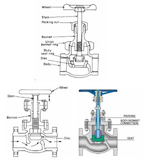
Globe valve is a valve designed to control the flow of fluid. Examples of use include: Faucet valves of this type used in home or in the common room is a spin cycle. (Not a stick on - off just twist it 90 degrees, which is a ball valve) for the structure of a globe valve is shown in Figure 2 below.

Figure 2 Globe valve (a) the structure of a small valve (bottom) structure of the valve size.

216B 1 1/2" Angle/Globe Valve


HPV100G 1 inch Globe Valve (Threaded) TxT


globe valve is a valve in the direction of flow. By the side of the valve with the arrow indicating the direction of flow of the fluid that flows through it and out of it. Of the structure of the valve shown in Figure 2 can be seen that the liquid flowing through the valve will swerve several times, even if the valve is fully open it. The pressure drop across a globe valve above the gate valve to close - open the valve is closed - open the disk (the disk or disc is the same) or plug is placed in alignment with the direction of flow. (In the direction of flow is from left to right) with openings that are aligned with the direction of flow as well. When the fluid flow into the valve body. Fluid will be forced to swerve to the bottom and top. Flow through the spaces between the openings on the disk / plug the size of the gap by moving the disk / plug up - which on a disk / plug the rise. Space is more open. Fluid will flow faster.


B and K Industries 106-004NL 3/4-Inch Low Lead Globe Valves


The relationship between flow rate of fluid flow through the valve with the motion of the disk / plug depends on the design shape of the opening and the bottom of the disk / plug the disk / plug that does not require any form. a flat plate. May have a curved or conical cutting head or head to form any time by using the proper format, we were able to valve relationship between flow rate and distance of motion of the disk / plug in various forms. as a straight line. (That is, if the valve open 20% of the fluid is flowing at a rate of 20% of the maximum flow rate if the valve open 65% of the fluid is flowing at a rate of 65% of the maximum flow rate) or a valve that rate. The flow is almost full when the valves open for a little time. (When the valve is opened slightly. Fluid to flow through the valve with high flow rate is almost double the maximum flow rate. When the valve opens up further. Flow rate did not increase much because it is near the maximum flow rate) globe valve is a valve for adjusting flow rate.

From Figure 2 it can be seen that the pressure of fluid acting on a disk / plug it in the direction of motion of a disk / plug that is located in the axis of the shaft valve (stem) of the valve through the stem valves. to a disk / plug is attached to the seat of the openings (the seat is a soft material over the disk / plug to provide a secondary disk / plug close to the seat to prevent leakage. (That is, to act as a gasket), and also prevents the disk / plug is damaged when it is pressed to attach to the skin opening) is not the pressure of fluid in the pressure plate disk / plug to attach to the seat just in case. The gate valve is why the pressure on the upstream and downstream are very different when the valve closes the opening of globe valve is easier than opening a gate valve, and by relying on competitive pressure plate disk is attached to seat them. The globe valve is closed tightly over the gate valve (as long as the surface of a disk with a seat to no damage).

A globe valve are designed to provide a disk / plug is firmly attached to the valve stem. I rotate them. This is to a certain position of the disk / plug exposed to the same location on every time the valve seat. In order to make a disk / plug itself has to wear a uniform. (Just as we need to switch the tires on a 10,000 km run to me. I know that I ever noticed it or not. Right-powered car steering wheel. (Most of our cars) right side tire will wear faster than the other wheels. Front tire and will wear faster than the rear).

Disadvantages of a globe valve in addition to having a high pressure drop. The size and weight of the valve is greater than that of the gate valve globe valve is the larger size and heavier as well. For this reason, in the case of pipes, large pressure on the upstream and downstream are a lot of the globe valve size will cause a pressure drop in the pipe and having a base of the valve that is stronger than a gate valve or the case. the hot fluid. (Ie piping, steam) at the downstream of the pipe is cold, which in the beginning to gradually warm the pipe on the downstream, the heat up slowly to prevent thermal shock or water hammer (in the case of fuel, water), made possible by to gradually open the valve at least once (crack open) until the tube starts to heat up. And increments it so that the flow control at this scale, a large globe valve be bad. The solution is done by using a gate valve in the closing - the main pipeline. (Such as a main pipeline with 12-inch) and a globe valve is in the pipeline bypass, which is smaller than the main pipeline (the pipeline bypass may have a 1-inch) and indirectly through a gate valve to be as shown in Figure 3, when The open tube will begin to gradually open the globe valve on the pipeline bypass is when the pressure or temperature in the downstream is the appropriate level, then it will open a gate valve that is located on the main pipeline and close. globe valve on the pipeline bypass.

In the case of a solid mixed with other fluids. Solid residue on the surface, it may cause problems, globe valve seat is not completely closed, such as gate valve.
Figure 3 is a globe valve in the bypass pipe to assist in opening a large pipe with a pressure / temperature in the downstream and upstream c are very different.

Gate valve

0 ความคิดเห็น
1. Gate valve.

Gate valve is a valve that is most widely used one. If I do not know how I try to look at the water meter home. (Hope that I have used tap water), which pipes water to separate from the main pipe. Before the meter will be off valve - open one. This valve is a gate valve (the valve, we heard it was a "gate"), perhaps it may install a gate valve on the output of the meter as well. However, some of which will install the check valve (the valve between the reverse flow) into the outlet of the meter. The gate valve must be installed before removing the meter from the meter to be removed. (Whether to repair or cut off the water because they do not pay the water bill).


The structure of the valve will be part of the disk (disk or a gate, see Figure 1) that is slightly larger than the diameter of the pipe. Up - down in the direction perpendicular to the direction of flow. When the valve is in closed position. The upstream pressure of the fluid will push the disk to lean with the body of the valve on the downstream side of the sealed fluid to flow through.

Advantages of the gate valve is wide. (Measured in the direction of flow) is not much space to install a small pressure loss (pressure drop) across the valve is very low when the valves fully open. Suitable for the type - open This valve is not suitable for use in flow control because the relationship between the length of the valve opening and flow rate is not good. (That is, some of the valve to move a little so that the flow rate changes. However, some of the valve to move a lot, but the flow rate changed only slightly) and is not suitable to open narrowed or slightly (crack opening) as the hand wheel, just not one we just feel that the fluid begins to flow through it. stops rotating. (You know it occurs when the fluid was flowing through a small opening between the seat ring below the disk), because while the valve is opened slightly. Fluid flows through a very high speed. And low pressure (pressure head is changed to velocity head) will cause the disk to vibrate violently enough to cause the disk or seat of the body that cause wear. This will not be able to close the valve to close again.


Figure 1, the gate valve type (left) Rising spindle gate valve, and (right) Fixed spindle gate valve of the core or stem is responsible for part of the disk (the that across the flow) on (to open) or down (to close) valve is visible rising spindle axis appeared to protrude from the center hole on the hand wheel to rotate the valve to open. You can see the sink into the hole in the middle of the hand wheel on the valve to close by the hand wheel is located on the same level. The valve fixed spindle and the disk is moving up - and down the spiral of the stem inside the bonnet on a rotating spindle which is not that he handed out roughly when the valve is in a position to open the valve rising spindle, it has many advantages. Just look what I know now that the valve is open or closed position. By the knowledge that emerges from the middle of the hand wheel lubrication and can be easily helix

Master Lock 482 Rotating Gate Valve Lockout


In addition, the pressure between the upstream and downstream of the valve in the closed position is very different. The valve opening can be difficult. Because the upstream pressure will press the sheet firmly against the body of the valve plate to move the disk moves in a direction perpendicular to the pressure is difficult. (I took one or more people standing on the mat. Then you pull the mat out. He failed, but if you have 10 people to stand up on the mat and then give you a surge of new mats. This time, you can not do that because there is not enough) in this case, the globe valve closing - the better.

Another type of event that caused the problem with the gate valve is used to mix liquids with suspended solids. (One example in the petrochemical industry and slurry from the slurry polymerisation. For example, in PE PP plastic, etc.) The problem occurs when the valve is located between the solid particles are left at the bottom of the disk of the valve seat and the valve does not close it. In this case, the ball valve is more appropriate.

Monday, November 28, 2011

Pressure Control Valves

0 ความคิดเห็น
Classification of the pressure control valve (Pressure Control Valve).
Pressure control valves can be divided into several types of behavior in high.
Hydraulic, with a different main functions. And purpose of use, but the.

The valve is similar. Is the pressure of the fuel cycle in order to allow the valve to act or work.
This has both direct and indirect control is as follows.


1. Valves limit pressure (Pressure relief valve).
2. Safety Valve (Safety valve).
3. Brake Valve (Brake valve).
4. Valve, the task sequence (Sequence valve).
5. Valve weight control (back pressure, Counter balance valve).
6. Valve discharge an obligation (Unloading valve).